How to Identify Electronic Components on a PCB
Printed Circuit Boards (PCBs) may look difficult at first glance, with tiny components and complicated pathways, but once you learn how to identify electronic components, it transforms into something much more hassle-free to understand & repair. Whether you're a technician, student, or buyer glancing for quality PCBs, this blog from Pulraj Electronics Pvt. Ltd. will help you grasp the fundamentals of electronic module identification with detailed examples, samples, and tips.
Why It’s Pivotal to Identify Electronic Components on a PCB
PCBs form the heart of entire electronic devices—from mobile phones and computers to industrial equipment and smart appliances. Every section on a PCB has a distinct tradition.
Electronic component identification is necessary for:
- Troubleshooting and Repairs
- Quality Control and Testing
- Design and Prototyping
- Choosing the Exact Components for Projects
At Pulraj Electronics Pvt. Ltd., we manufacture PCBs with appropriate labeling, ESD safety, and high-performance standards (ISO 9001:2015 endorsed), generating them user-friendly for engineers and buyers.
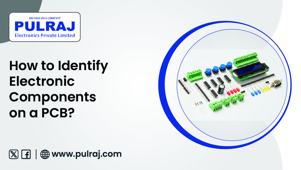
Regular Components You’ll See on a PCB
Let’s survey the most common electronic component identification found on PCBs, and how to identify them by outward look, codes, and markings.
1. Resistors (R)
- Symbol on PCB: R (e.g., R1, R15)
- Visual Clue:Cylindrical with color bands (through-hole) or small black rectangles (SMD)
- How to Identify:
- Use the color code to read resistance value
- SMD resistors have 3- or 4-digit numbers printed
- Function: Limits electrical current in a circuit
2. Capacitors (C)
- Symbol on PCB: C (e.g., C1, C7)
- Visual Clue:
- Disk-shaped (ceramic)
- Small cans (electrolytic)
- SMD versions look like black or tan rectangles
- How to Identify:
- Labeled with virtues in µF, nF, or pF
- Electrolytic types show polarity (+/-)
- Celebration: Stores and releases electrical drive
3. Diodes (D)
- Symbol on PCB: D or CR (e.g., D3, CR1)
- Visual Clue: Black cylinder with a silver/white stripe (through-hole) or small black chip (SMD)
- How to Identify:
- Stripe indicates cathode (-)
- SMD markings may have part numbers like 1N4148
- Observance: Allows current to flow in one direction only
4. Transistors (Q or T)
- Symbol on PCB:Q or T (e.g., Q2, T1)
- Visual Clue: 3-pin components, can become black with flat/spherical best
-
How to Identify:
- Marked with numbers (e.g., BC547)
- Some have a metal tab or heat sink
- Festivity:Improves or switches electronic indicators
5. Intertwined Circuits (IC or U)
- Symbol on PCB IC or U (e.g., U1, IC3)
- Visual Clue:Black rectangular chips with many legs/pins
- How to Identify:
- Part numbers like NE555, LM324, ATmega328
- Some have dot/line to show Pin 1
- Observance:Performs challenging tasks like signal processing, control, logic, etc.
6. Inductors (L)
- Symbol on PCB:L (e.g., L1)
- Visual Clue:Wire coils or surrounded cylinders
- How to Identify:
- Marked with inductance value (µH, mH)
- Ceremony: Stores vigor in a glamorous field
7. Connectors & Headers (J or CN)
- Symbol on PCB:J or CN (e.g., J1, CN5)
- Visual Clue: Plastic with multiple pins or sockets
- How to Identify:
- Used to connect skill, data, or lights
- May become stamped with voltage or signal names
- Tradition: Allows connection to further PCBs or systems
Tips for User-friendly Electronic Constituent Identification
Use a Multimeter
For unknown or toasted-out components, a multimeter helps measure resistance, capacitance, or diode observance.
2. Refer to Section Datasheets
Search for part numbers on Google to find extensive datasheets with pinouts and specifications.
3. Use a PCB Viewer Tool
If you have a PCB design file, use tools like Gerber viewers or EAGLE/Altium to see imprinted components digitally.
4. Visual Inspection with AOI (Automated Optical Inspection)
At Pulraj Electronics Pvt. Ltd., we use AOI Machines to detect missing or misaligned components automatically—ensuring every single PCB is painless to read and error-free.
Conclusion: Partner with the Experts in PCB Quality
Realizing how to identify electronic components on a PCB not only raises repair and design economy but also ensures that you're working with high-quality hardware.
At Pulraj Electronics Pvt. Ltd., we make PCBs with perfect precision, titled components, tested under ISO 9001:2015 standards, in ESD-safe and dust-free environments. With leading tools like Automated Optical Inspection Machines, we assure your PCBs are uncomplicated to read, build, and maintain.
Looking for reliable, well-marked, and durable PCBs?
Email: info@pulraj.com
FAQs
1. How do I identify electronic components without labels?
Use the factor's shape, pin count, and markings. A multimeter or test circuit can additionally help identify ideals and types. When in doubt, consult a datasheet.
2. What are the most common components on a PCB?
Resistors, capacitors, diodes, ICs, and transistors are among the most steadily used components in both analog and digital circuits.
3. Can I learn section identification without a design degree?
Too much! Anyone can learn it with some practice, visual guides, and easy tools. Many hobbyists and technicians master this with hands-on proficiency.
4. Too much! Anyone can learn it with some practice, visual guides, and easy tools. Many hobbyists and technicians master this with hands-on proficiency.
Knowing which piece does what helps locate the fault and repair or replace it precisely, saving both time and cost.